TSoil
Internal ATD Tsoil Demonstration Array Info.
-
Description and Overview
- This file is a temporary repository for testing and implementation information concerning the CME Project Tsoil demonstration array using CrossBow Mica2 sampling data from LM20 temperature sensors
Example Tsoil Mote output Message:
	Application uses Message type	= 0x0A (10)
	and uses TOS group-id		= 0x41 (65),
	with # data bytes in a 'packet'	= 0x1C (28) Maximum allows by tos=29
	Within the Packet below:
	This example has mote-id	= 0x0A (10)

NOTE:	actual packets have a FRAMESYNC character prepended: 0x7E
        and a 2-byte CRC appended, with apparently another
	framesync added at the end.
	Here is another output of the same type messages generated by
	a Procomm script ($PAM/pc_files/ProcommScripts/hexDumpIngest)
	that simply blurts out hex chars:


Raw Tsoil Packet: 37 chars from base-station-mote

           type  len     seqno.  nreadings
sync  addr  | grp |  .id.. | nsets| nchan
 |    |     |  |  |  lo-hi |  |   | |  lo-hi lo-etc...
7E 42 FF FF 0A 41 1C 0A 00 02 01 14 07 9C 0B BF
15 71 15 61 15 47 15 40 15 56 15 00 00 00 00 00
00 00 00 A7 57 7E
time1..| |crc| sync

hex
FFFF =	tosaddr  = buf[2]<<8) + buf[3]		; TOS-AM address (not used?)
0A =	msgtype  = buf[4]			; TOS-AM message type: see TsoilMsg.h for decl.
41 =	groupid  = buf[5]			; TOS-AM group id #
1C =	ndata    = buf[6]			; #chars in data portion
000A =	moteid   = (buf[8]<<8) + buf[7]		; 2-bytes lsb/msb ordered in buf
02 =	seqnum   = buf[9]			; 1-byte  watchdog counter goes 0-99 (0x063)
01 =	nsets    = buf[10]			; 1-byte  # sample-sets per message
14 =	nreadings= buf[11]			; 1-byte  # adc readings per sampleset (20)
07 =	nchan    = buf[12]			; # channels included
0B9C =	vbatt    = (buf[14]<<8) + buf[13]       ; 2-bytes lsb/msb, mV
15BF =	tsoil[0] = (buf[16]<<8) + buf[15]       ; 2-bytes lsb/msg, degC*100
1571 =	tsoil[1] = (buf[18]<<8) + buf[17]       ; ..NOTE these sensors inputs were open!
1561 =	tsoil[2] = (buf[20]<<8) + buf[19]       ;
1547 =	tsoil[3] = (buf[22]<<8) + buf[21]       ;
1540 =	tsoil[4] = (buf[24]<<8) + buf[23]       ;
1556 =	tsoil[5] = (buf[26]<<8) + buf[25]       ;
00000000 = timeval[0] = (buf[27]<<24) +		; NOT USED...LYNETTE'S THING
		     (buf[28]<<16) +
		     (buf[29]<<8)  + buf[30];
00000000 = timeval[1] = (buf[31]<<24) +		; NOT USED...LYNETTE'S THING
		     (buf[32]<<16) +
		     (buf[33]<<8)  + buf[34];

        ix              = ndata+7		; 0x1c+7 = ix = 35
57A7 =	crcval  = (buf[ix]<<8) + buf[ix+1]      ; tos value added
7E =	sync
Description of TOS Active Message Packet Format
See Also: Example Messages Above
          Serial Line Communication via TinyODdoc page

        Note:   tinyos-1.x/tos/types/AM.h
	        which defines:

        #define TOSH_DATA_LENGTH 29	.......0x1D, effects pkts such as OscopeMsg.h
        #define TOSH_AM_LENGTH 1
        #define TINYSEC_MAC_LENGTH 4
        #define TINYSEC_IV_LENGTH 4
        #define TINYSEC_ACK_LENGTH 1

        typedef struct TOS_Msg
        {
          /* The following fields are transmitted/received on the radio. */
          uint16_t addr;
          uint8_t type;
          uint8_t group;
          uint8_t length;
          int8_t data[TOSH_DATA_LENGTH];	THIS IS THE TSOIL MESSAGE PACKET
          uint16_t crc;

          /* The following fields are NOT ACTUALLY TRANSMITTED or received
           * on the radio! They are used for internal accounting only.
           * The reason they are in this structure is that the AM interface
           * requires them to be part of the TOS_Msg that is passed to
           * send/receive operations.
           */
          uint16_t strength;
          uint8_t ack;
          uint16_t time;
          uint8_t sendSecurityMode;
          uint8_t receiveSecurityMode;
        } TOS_Msg;
Using Sensors and Sampling Limitations ...
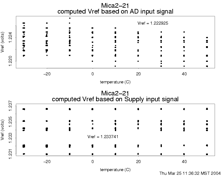
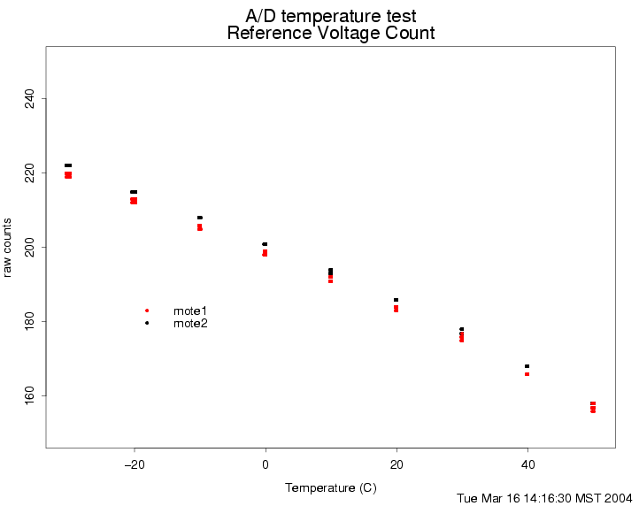
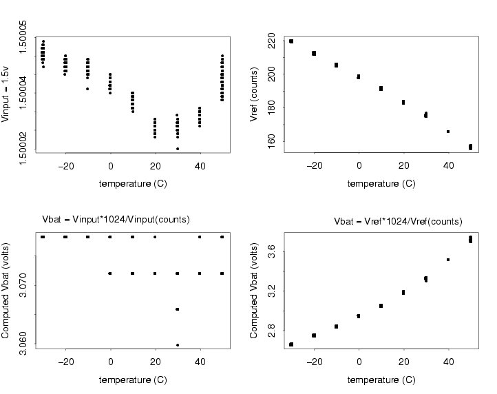
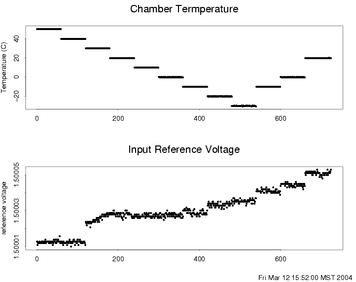
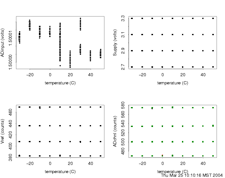
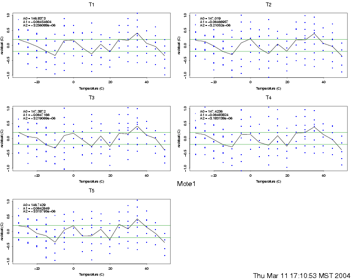
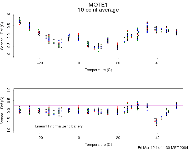
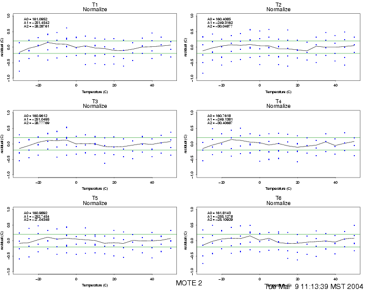
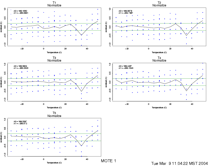
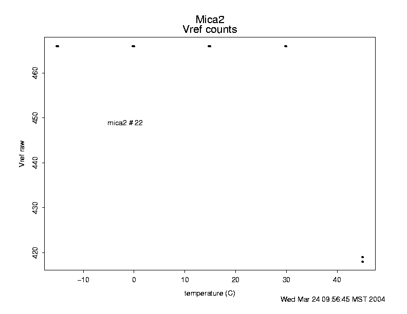
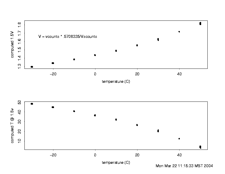
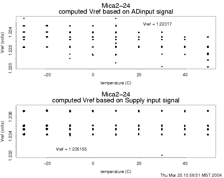
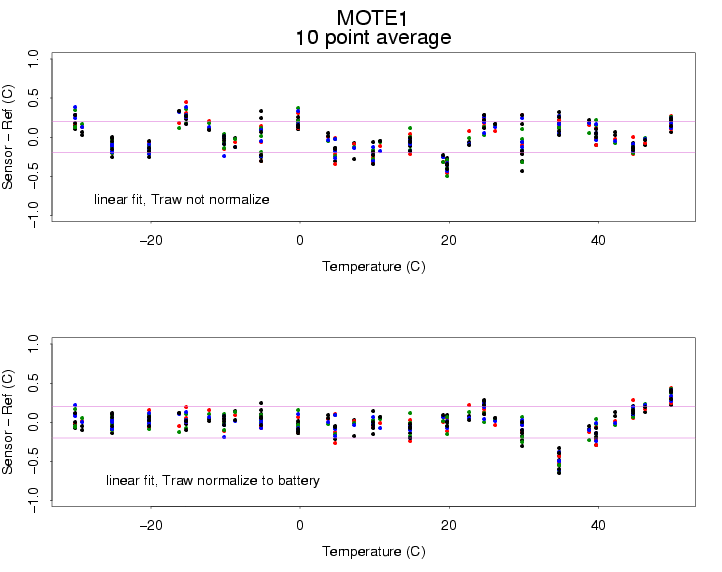
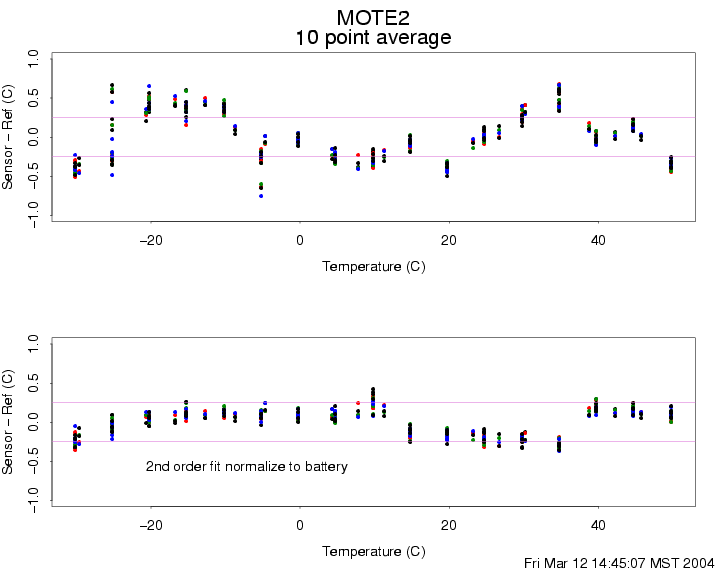
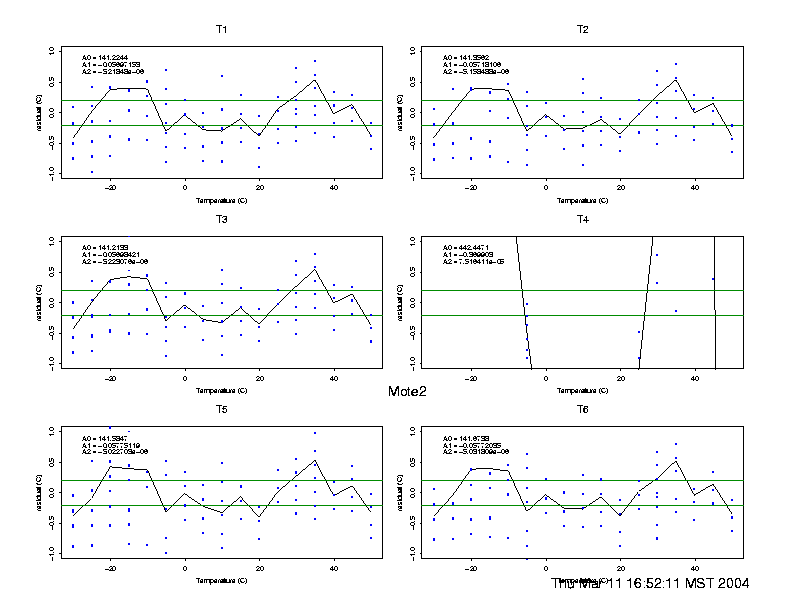
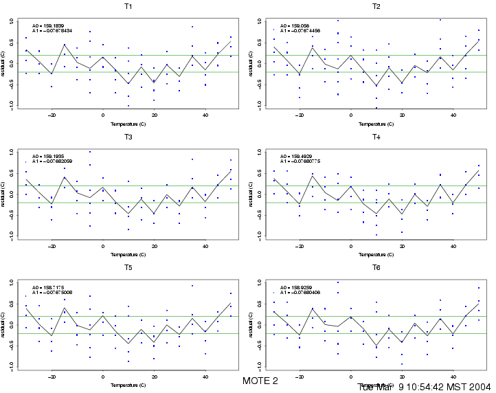
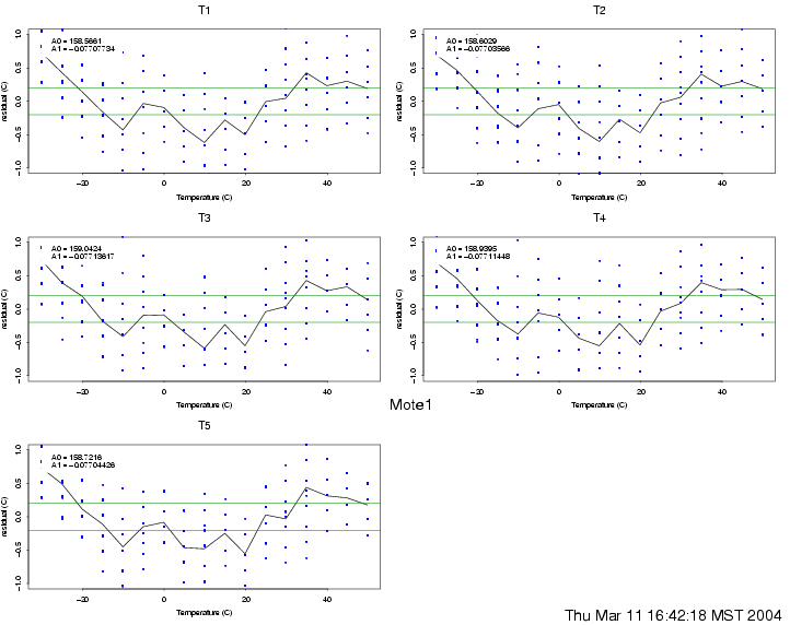
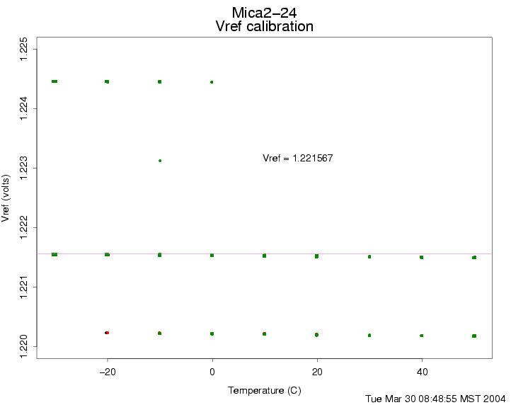
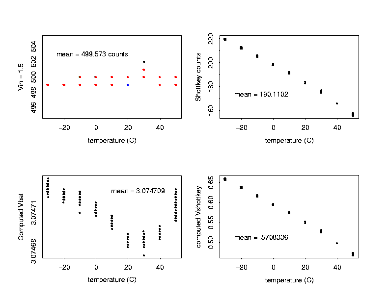
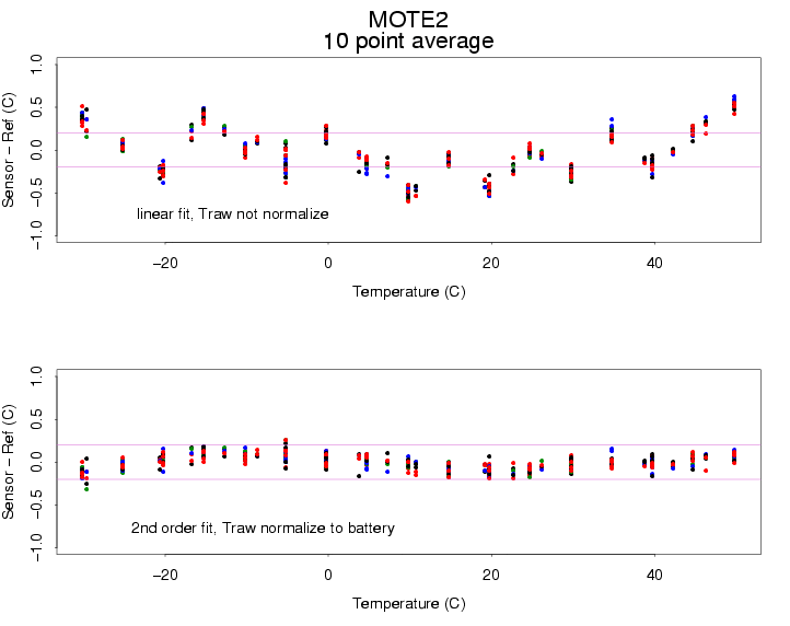
- LM20 Use:T = -1481.96 * sqrt( 2.192e+6 + (1.8639-Vo)/3.88e-6 ) Accuracy: +- 1.5degC to +-4degC at 30degC +- 2.5degC to +-5degC over -55 to 130 Output for Range -5 to 30: ~1.9 to 1.5 vdc Resolution: MicaADC ~=3.3v/1024 = 3.2mV/bit ~= .273 degC/bit With Oversampling: Niquist resolution goes up ~sqrt(#samples) for 10 samples/message = .273/sqrt(10) ~= .08degC resolution - ADC Mica2 Channels 'on-board' 10bit ADC (1024 bits)ratio Metric to vbatt accuracy: +- 2 lsb AD0=RSSI Output from ChipCon Radio, no excitation reqd. AD1=Thermister Option NOT INSTALLED ON OUR MICA2's Probably would be 10kohm YSI44006 as on MTS101CA sbi( PORTA, 7 ) Turns on exicitation denote 'THERM_PWR' pin sample ADC1 cbi( PORTA, 7 ) Turns it off AD7=Vbatt can be shared but has 10k-ohm impedance Excitation is from Atmega 'PA5' pin on Mica2. sbi( PORTA, 5 ) Turns on exicitation denote 'BAT_MON' pin sample ADC7 cbi( PORTA, 5 ) Turns it off AD1-6 available Manual Control of ADC perhaps when performing: call ADC.getContinuousData(); sbi( ADCSR, ADEN) Turns ADC on cbi( ADCSR, ADEN) Turns ADC off look in tos/platform/mica2/hardware.h for useful declarations TOS_ADC_CC_RSSI_PORT = 0, TOS_ADC_VOLTAGE_PORT = 7, Mica2 Control Mica2dot Control ADC-0 RSSI RSSI ADC-1 Vref PW7-low, PW5-high ADC-2 ADC-3 ADC-4 ADC-5 ADC-6 ADC-7 Vref PA5-high ADC conversion Rate: From tos/interfaces/ADControl.nc which maps down to .. /** The Atmega processor ADC register Prescaler * Sets the sampling rate of the ADC. * They are the lower three bits in the ADCSR register. * The rate parameter may use the following macros or * its own value (0-7) from the description below. * TOS_ADCSample3750ns = 0 * TOS_ADCSample7500ns = 1 * TOS_ADCSample15us = 2 * TOS_ADCSample30us = 3 * TOS_ADCSample60us = 4 * TOS_ADCSample120us = 5 * TOS_ADCSample240us = 6 * TOS_ADCSample480us = 7 * @param rate 2^rate is the prescaler factor to the ADC. * The rate of the ADC is the crystal frequency times the * prescaler, or XTAL * 2^rate = 32kHz * 2^rate. * * @return SUCCESS if successful */ command result_t setSamplingRate(uint8_t rate); Jtag uses AD4-AD7, must be turned off via fuses: NOTE The Atmega JTAG fuse should be disabled to get high accuracy voltage measurements for the reference voltage. The JTAG port shares ADC channel 7 which is also used for the voltage ref input to the adc. Using the most recent version of uisp you can turn on/off the JTAG fuse:. fuse_dis--->"uisp -dprog=dapa --wr_fuse_h=0xD9" fuse_en --->"uisp -dprog=dapa --wr_fuse_h=0x19" Do this by editing: apps/Makelocal PROGRAMMER_EXTRA_FLAGS := --wr_fuse_h=0xD9 Radiometric Sampling limitations: depend upon vbatt for vref to adc, but Mica2/Dot include a separate vref. mica2 = adc7 1.223v mica2dot = adc1 .600v Shottkey Reference Diode must post-cal correct data based upon vb and vref Don't need to do this if your sensor is ratio metric also vbatt = vref*ADC_FS/reading = 1.223 * 1024/reading Mica2 = .600 * 1024/reading Mica2dot- Power Consumption
	Measured:
	    TinyPV Panel:  Isc=~20mA (ea.), Voc~=4.5V	Full Sun (800w/m^2?)
						=1.4V	Office Light
						=9.9V	2panels

	    Tsoil Mica2:   13.8mA	With LEDs, RF going
			   11.4mA	(nom. without power-down)
			    2.5mA	w.o LEDs, no RF
			    3.3mA	nominal power during DAQ, no RF
			   < .03mA	with PMEnable() power-down, no RF

			     .8mA	NOMINAL OPERATION
			  = 2.8mW
			(20adc readings, every 10-s, 5-min xmit with 10-sec
			'cmdlisten time')

	    RF Repeater:	(Mica2 to Maxstream Radio repeater)
		TOSbase on MIB510:	28mA
		MaxStream, Listen:	54mA
			   Transmit:	88mA
		Total,
		Listen:	 =  82mA @12.7V ~= 1.0 Watt
		Transmit = 105mA @12.7V ~= 1.5 W


	Battery: Rayovac Renewal Rechargeable Alkaline

	    1.5v nominal, can handle 400mA
	    Capacity vs normal alkaline:
	    'C'	~= 80% new, roughly 14 hours 3.9ohm ~= 4400mAh
		~= 55% after 5 cycles, 10 hours 3.9ohm ~= 3080mAh
		~= 30% after 25 cycles, 5.5hours 3.9ohm ~= 1700mAh

	    Endurance given the above assumptions:
		3000mAh/.8mA ~= 150 days
		That is without charging...is that true???
		This hard to believe based on very crude observation

	    Charger: World's dumbest solar charger!!!
		regulator: 3.9v zener (1n5228), with 10kohm lim. resistor
		and blocking diode (SDIO3 shottky, ~.3-.4v drop across)
		holds batt+ to about 3.5v for nominal 3.0 renewal.
		Observed the renewals generally floated up to about 3.3
		and held there.

	    See Also:	http://www.epa.gov/etv/pdfs/vrvs/06_vr_rayovac.pdf

	Notes:
	    Atmega output pins source 5-10mA
	    Stop Services to have them enter low power mode.
	    	When all services are stopped and Task Que is empty,
		TOS goes into Power Down, and
		Wakes up on next Event from TimerM.nc
- This file is a temporary repository for testing and implementation information concerning the CME Project Tsoil demonstration array using CrossBow Mica2 sampling data from LM20 temperature sensors
CME04 Publications
Data Access
Facilities & Instruments
